Logo CLIENT LOGIN | MANAGE ACCOUNT | ORDER STATUS | TRACKING | LOG OUT

Our Products

Shopping cart

Shopping cart  Shopping cart
0 Product(s) in cart
Total $0.00
» Checkout

Our services


  Facebook Houzz    
         

NOMMA Member

NADRA Member

credit cards


Installation Guide

Series 4100 Installation Guide for 1/8” Cable
Invisiware® Receivers with Push-Lock® Fittings

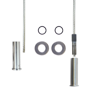
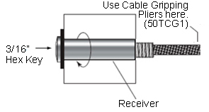
Materials/Tools Required____________________

* Cable Gripping Pliers — (50TCG1)
Used to grip the cable while tensioning
the end fittings without damaging the cable.
[OPTION: Use a piece of rubber hose with vice grips
around the cable to prevent scarring.]

* Cable Cutter 1/8” — (82T07)

* 3/16” Hex Allen Key

* Drill

* Drill Bits:

- 29/64”

- 5/32”
(if there are intermediate posts between
the terminating end posts or where the length of
the receiver or Pull-Lock® fitting you are using
is less than the thickness of the end post)

- 15/16” (if you wish to counterbore the wood
end post to recess the 11HW14 washer)

4100 Series Assembly

Drill Posts_________________________________________________________________________

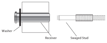
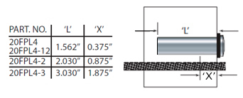
Terminating (end) post for Invisiware® Receivers

Drill a 29/64” hole from the back side of the end posts
where each cable will be installed. For a 1-1/2” or less square end post using a 1-1/2” long receiver, a 2” end
post using a 2” long receiver, a 2-3/8” end post using a
2-3/8” long receiver, or a standard 4x4 using a 3-1/2”
long receiver, drill the hole completely through the post.
For posts thicker than the length of the receiver, drill a
5/32” pilot hole completely through the post, then drill a 29/64” hole only through the back surface of the end
post (in the case of a wood post, to a depth a little
greater than the length of the receiver) but not
completely through the post.
Terminating (end) post for Pull-Lock® fittings

Drill a 29/64” hole from the back side of the end posts where each cable will be installed. For a 2”or less square end post, drill the hole completely through the post. For posts greater than 2” thick, drill a 5/32” pilot hole completely through the post, then drill a 29/64” hole only through the back surface of the end post (in the case of a wood post, to a depth a little greater than the length of the Pull-Lock® fitting) but not completely through the post.

Intermediate post or other element through
which the cable will pass between the end
posts

Drill 5/32” diameter holes lined up with
the holes in the end post through which the cable
will pass between end posts.


Install Invisiware® Receivers_____________________________________
  1. Slide the washer (black plastic for metal
    posts, 11HW14 stainless steel for wood
    posts) over the body of the receiver,
    then feed the receiver through the hole
    in the back of the post.

  2. By hand, screw the receiver body onto
    the swaged stud at least 6 full turns.
    Do not tension the cables at this point.
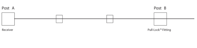
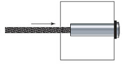
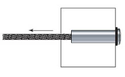
String the cable through the holes drilled in
your intermediate posts (or other elements
through which the cable passes between
end posts) and through the end post where
you will be installing the Pull-Lock® fitting.
See illustration below — Post A is the end post
to which the receiver is attached; Post B is the
end post to which the Pull-Lock® fitting is to be
attached.
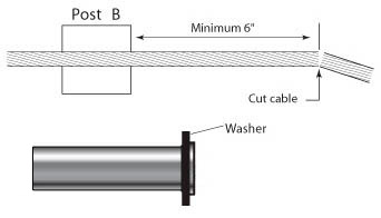
Install Push-Lock® fittings _______________________________________
  1. With the cable strung through the end post,
    cut the cable with a cable cutter (82T07), leaving enough cable extending out the back side of the post to be able to grasp the cable firmly with your hand (6” or more).


  2. Slide the washer (black plastic for metal posts, 11HW14 stainless steel for wood posts) overthe body of the Push-Lock® fitting.


  3. Pull the cable tight and mark the cable at a point 'X' from the backside of the post. Cut the cable at the mark using a cable cutter (82T07).


  4. Push the cable into the hole in the fitting as far as it will go (approximately 1-1/16"). Twist the cable in the right-hand direction (with the lay of the cable) as you push it into the fitting. You will feel it slide through the jaws inside the stud.


  5. Pull the cable to set the gripping action of the
    Push-Lock® fitting.


  6. Tension the cables.
    After all the cables have been installed in
    both end posts, tension the cables with the
    receivers on the other end to approximately
    150 lbs. per cable by holding the cable with
    cable gripping pliers (50TCG1) closely behind
    the stud. Turn the receiver clockwise with a
    3/16” hex key as illustrated at right.


    Note: Tension in sequence shown in the illustration at right, beginning with outside the cables and moving from side to side toward the center


© Copyright 2021 - CABLE ART INC.