| Series 6301 Installation Guide for 3/16” Cable Adjust-A-Body® Threaded Eye with Pull-Lock® Fitting |
|
| Materials/tools required____________________ * Cable Gripping Pliers — (50TCG1) |
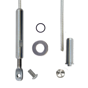 * Cut Off Wheel Kit — (11TCUTKIT) |
Drill Posts_____________________________________________________________________________ |
|
| Terminating (end) post for Pull-Lock® fittings Drill a 29/64” hole from the back side of the end posts where each cable will be installed. For a 1-1/2”or less square end post, drill the hole completely through the post. For posts greater than 1-1/2” thick, drill a 7/32” pilot hole completely through the post, then drill a 29/64” hole only through the back surface of the end post (in the case of a wood post, to a depth a little greater than the length of the Pull-Lock® fitting) but not completely through the post. |
Intermediate post or other element through which the cable will pass between the end posts Drill 7/32” diameter holes lined up with the holes in the end post through which the cable will pass between end posts. |
| Install Adjust-A-Body® Threaded Eye Tensioner___________________________________ |
||
|
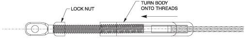
1. Attach the Threaded Eye tensioner to one |
2. Screw the lock nut onto the threads. 3. Slide the body onto the cable, threaded end 4. Turn the body by hand, onto the threads at |
|
 |
||
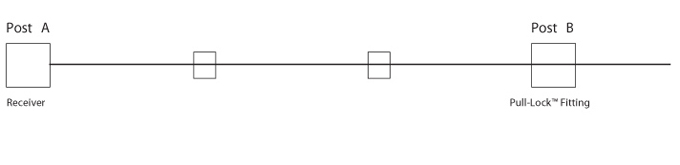
| String the cable through the holes drilled in your intermediate posts (or other elements through which the cable passes between end posts) and through the end post where you will be installing the Pull-Lock® fitting. |
See illustration below — Post A is the end post to which the tensioner is attached; Post B is the end post to which the Pull-Lock® fitting is to be attached. |
|
 |
||
| Install Pull-Lock® fittings____________________________________________________ | ||
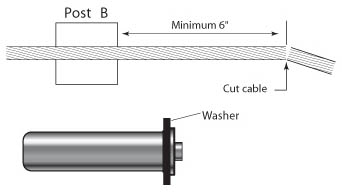
| 1. With the cable strung through the end post, cut the cable with a cable cutter (82T13), leaving enough cable extending out the back side of the post to be able to grasp the cable firmly with your hand (6” or more). 2. Slide the washer (black plastic for metal posts, |
 |
|
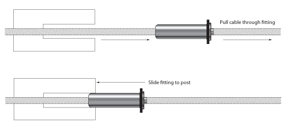
| 3. Push the cable into the hole in the front of the Pull-Lock® fitting, and pull the cable through the fitting. Twist the cable in the right-hand direction (with the lay of the cable) as you push it through the fitting. Then slide the fitting along the cable and up to the back side of the post. |
||
 |
||
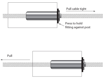
| 4. Hold the cable with one hand and slide the Pull-Lock® fitting into the hole in the post. Press the back of the fitting to hold it securely in the post and pull the cable through the fitting until it is as tight as you can make it. 5. Pull the cable to set the gripping action of the |
 |
|
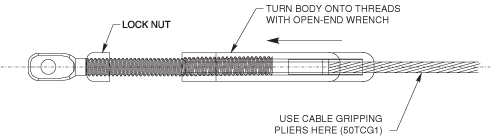
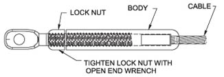
6. Tension the cables. After all the cables have been installed in both end posts, tension the cables on the other end to approximately 150 lbs. per cable by gripping the cable with the Cable Gripping Pliers (50TCG1) closely behind the stud as you turn the body onto the threads with a 7/16” open-end wrench. |
||
 |
||
|
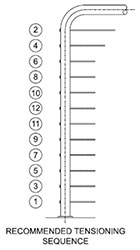
Note: Tension in sequence shown in the illustration at right, beginning with outside the cables and moving from side to side toward the center. |
 |
|
7. With (2) 7/16” open-end wrenches, tighten the lock nut against the body of the fitting. |
 |
|
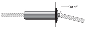
| 8. Cut the cable flush with the hole in the back of the Pull-Lock® fitting, using a cut-off wheel. |
 |
|
| 9. Press the cap onto the lip of the Pull-Lock® fitting. | 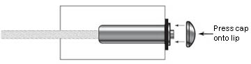 |
|