| Kit 6403 Series Installation Instructions for 4 x 4 Wood Posts |
||
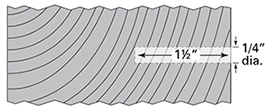
Hole size for 3/16” dia. cable installation: For both 1/8" dia. cable: |
 |
|
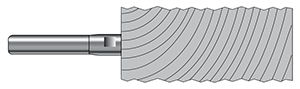
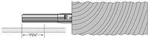
Drill 9/32” hole 1-1/2” into the inside of the |
 |
|
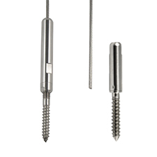
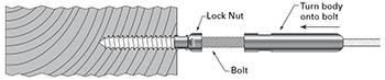
| 1. Install the tensioning end first with the Adjust-A-Body® with Hanger Bolt (A-JB6) by driving the hanger bolt / lag end into the 1/4” pre-drilled pilot hole in your end post using a 1/4” open-end wrench or hanger bolt driver (order separately). |
||
| 2. Screw the lock nut all the way onto the 2” long threaded end of the bolt. |
||
| 3. Thread the body with the cable attached onto the threaded end of the bolt and turn halfway along the threads. |
 |
|
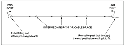
| 4. Run the bare end of the cable through all your intermediate posts and to the end post where you will be installing the Push-Lock® fitting. |
 |
|
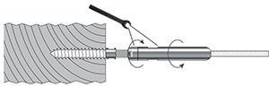
| 5. Use a hex wrench to drive the lag section of the fitting into your pre-drilled pilot hole. |
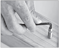 |
|
| 6. Thread the Push-Lock® coupler onto the lag and tighten with 7/16” wrench. | 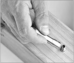 |
|
| 7. Make sure the post side of the Push-Lock® lag is flush against the post. |
 |
|
| 8. Pull the cable tightly along the side of the
fitting and mark the cable 1-3/16” from the end of the fitting opposite the post. Mark and cut the cable on your mark. |
 |
|
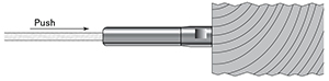
| 9. Push the cable into the hole in the fitting as far as it will go (approximately 1-1/16”). Twist the cable in a right hand direction as you push it into the fitting. |
 |
|
| 10. Go to the other end and tension the cable by holding it to prevent the cable from turning while you turn the Adjust-A-Body® with a 7/16” open-end wrench. Be careful to protect the cable from damage while tensioning the Adjust-A-Body®. |
||
| 11. Turn the lock nut against the body and tighten with open-end wrenches. Leave about 1/2” of thread exposed when tight for future tensioning if needed. |
 |
|
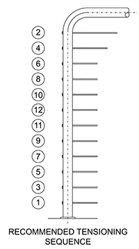
| 12. Tension in sequence, beginning with the
outside cables and moving from side to side toward the center. |
 |
|
