- Pull-Lock®
- How It Works
- Assembly Instructions
 |
 |
| Pull-Lock® | GRIP | 316SS |
| CABLE DIA. |
LENGTH OPTIONS | FOR WOOD, USE WITH WASHER NO. |
||
| L= 1.810" | L= 2.030" | L=3.030 | ||
| 1/4" | 20FPUL8-18 | 20FPUL8-2 | 20FPUL8-3 | 11HW16 |
| Designed for use with 1x19 left hand lay strand only. |
| Please click part number to order. |
 |
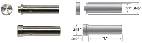
| How It Works Use with metal or wood posts Pull-Lock® fittings are used with pipe and with round, square, or rectangular metal tubing. When used with an end post larger than 1-1/2” in thickness, the Pull-Lock® fitting is hidden inside the end post, with only the head exposed on the outside of the post. Pipe ends are counterbored, so the full perimeter of the screw cap head rests on a flat surface in the pipe. The head rests on the outside wall of a flat-sided metal post. A plastic washer is included and acts as a scratch-resistant barrier between the screw cap head and the metal post. For wood applications, also order Stainless Steel Washer, 11HW16 washer. |
| Pull-Lock® Stop-end (non-tensioning) Fittings Installation Instructions |
|||
 |
|||
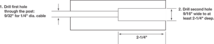
| Make sure the holes are drilled properly in the posts where you will be installing your fittings. If you are installing the fittings in a metal railing; Drill the end posts 9/16" through the tube wall(s). If you are using wood end posts; Make sure the holes are drilled properly in the posts where you will be installing your fittings. (It is best to drill the pilot hole all the way through from the inside out.) Then drill a 9/16" hole from the back side of the post at least 2-1/4" deep (deeper if you are counterboring for the over-sized washer). |
|||
 |
|||
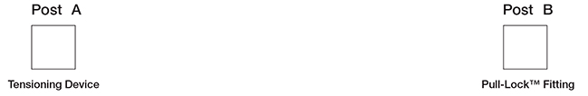
| Step 1 |
Install the tensioning device(s) at Post 'A' first. | ||
 |
|||
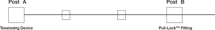
| Step 2 | Run the cable through the intermediate posts (if any) and through Post B where you will be installing the Pull-Lock® Fittings. |
||
 |
|||
| Step 3 | Cut the cable with a cable cutter, leaving enough cable extending out from the back side of the post to be able to grasp the cable firmly with your hand (6” or more). | 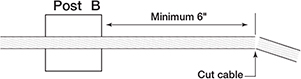 |
|
| Step 4 | Slip the washer over the body of the Pull-Lock® Fitting (11HW16 washer for wood posts, 20HWD8B black Delrin® washer for metal posts). | 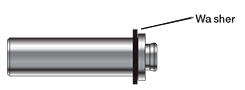 |
|
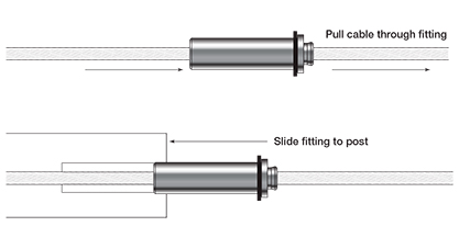
| Step 5 | Push the cable into the hole in the front of the Pull-Lock® Fitting and pull the cable through the fitting. Twist the cable in the clockwise as you push it into the fitting. Then slide the fitting along the cable and up to the back side of the post. | ||
 |
|||
| Step 6 | Hold the cable with one hand and slide the Pull-Lock® Fitting into the hole in the post. Press on the back of the Pull-Lock® fitting to hold it securely in the post and pull the cable through the fitting until it is as tight as you can make it. | 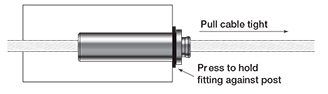 |
|
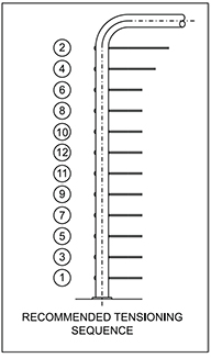
| Step 7 | Tension the cable with the tensioner installed on the end post (Post A) at the other end of the cable run, after all the fittings have been installed in both end posts. Tension all cables in sequence. | ||
| Step 8 |
Tension all cables to desired amount in sequence, begining with the outside cables, moving up and down toward the middle. As you tension each cable, give it a sharp pull downward mid-span to help set the wedges, then re-tension as necessary in the same sequence. |
 |
|
| Step 9 | Cut the cable flush with the hole in the back of the Pull-Lock® Fitting, using a cut-off wheel. | 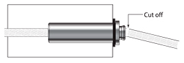 |
|
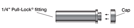
| Step 10 | Press the cap onto the lip of the Pull-Lock® Fitting. | 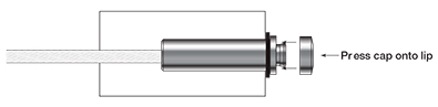 |
|